Страница 1 из 1
TT MK1 boost wire
Добавлено: 28 сен 2020, 12:34
Pistou
Hello,
thanks to Ian I know I could solder boost wire to Analog pin&, I was wondering why in the tutorial PDF file we got this:
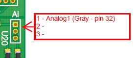
the 32 pin is empty based on excel file....
thank you
TT MK1 boost wire
Добавлено: 06 окт 2020, 20:19
autopilot
Hi.
In manual present internal connection from ColorMFA to cluster.
For display "boost" value on screen need also add one wire from engine ECU socket to cluster socket. Different engines have different wire diagram (this info not present in manual).
More about this you may read here:
Подключение наддува / Boost connection
TT MK1 boost wire
Добавлено: 07 окт 2020, 10:11
Pistou
Hello Autopilot,
I am gonna use the boost sensor wire yes but do I have to connect Analog 1 to gray pin 32 yet ?!
Analog 1 => Gray pin 32 AND Boost wire sensor purple gray
OR
Analog 1 => Boost wire sensor purple gray
Thank you
TT MK1 boost wire
Добавлено: 07 окт 2020, 12:47
autopilot
Two variants:
1.
Analog 1 -> Gray pin 32 (internal cluster socket)
Gray pin 32 (external cluster socket) -> wire to ECU
2.
Analog 1 -> wire to ECU
If you need remove cluster after connect "boost" wire, you may not use variant 2. Because if you dirrectly connect wire from Analog1 to ECU, cluster cannot be removed in future without disconnect this wire (or need add additional connector to this wire).
TT MK1 boost wire
Добавлено: 07 окт 2020, 12:50
Pistou
Ok this is why... Now I get it and I will use this since I already soldered a wire on the cluster:

Thank you